The STM8 series of microcontroller’s are extremely budget friendly and provide great features for the money. If you are using SDCC as the compiler for your projects. You have probably found examples for peripherals like timers quite scarce. Here you can see an example of the STM 8-Bit Timer Configuration
Recently I wanted to understand how the basic 8-bit timer TIM4 on the STM8S103F3P6 worked. It took me some time to fully get to grips with, partly for not paying enough attention to the reference manual and datasheet, but also by looking at a bad example I found on Github.
The example I saw for configuring the prescaler of the timer advised to configure the prescaler with a value from one of 128, 64, 32, 16, 6, 4, 0. Using a fx2lafw based logic Analyzer and Pulseview I was seeing some odd results. The timer would overflow before I expected it to. It turns out configuring the prescaler with these values is incorrect.
Correct Prescaler Configuration
According to the datasheet the TIM4_PSCR register only has 3 configurable bits. They range from bit 0 to bit 2
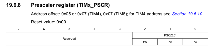
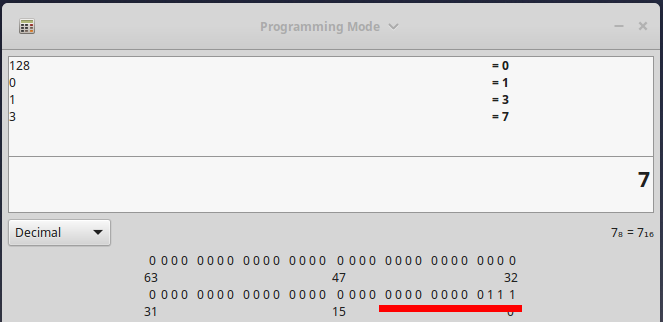
If only 3 bits can be configured, you can not write a value of 128 as this would need an 8 bit wide register. Instead the maximum value we can write is 7 which would set bits from 0 to 2.
This means the only values we can set for this timer are 1-7. After some trial and error I figured out that these values represent the division of the input clock to the timer. The examples below are based on a input frequency of 16mhz.
 0x07 = /128 8us      per tick, 2.048ms per overflow
 0x06 = /64  4us      per tick, 1.024ms per overflow
 0x05 = /32  2us      per tick, 512us   per overflow
 0x04 = /16  1us      per tick, 256us   per overflow
 0x03 = /8   0.5us    per tick, 128us   per overflow
 0x02 = /4   0.25us   per tick, 64us    per overflow
 0x01 = /2   0.125us  per tick, 32us    per overflow
 0x00 = /0   0.0625us per tick, 16us    per overflow
I hope this helps when trying to configure the timer, as you can see from my example the maximum delay with a single over flow and a 16mhz clock is 2.048ms. You can however count multiple overflows in the ISR to make a bigger delay.
If you have found this useful or would like me to explain this in greater detail please leave a comment.
Thanks for infos. I think the prescaler values are power of 2
2^0=1;
2^1=2;
2^2=4;
.
.
.
.
.
2^7 = 128;
And division to 0 is undefined in mathematic.